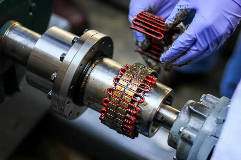
A shaft coupling is one of the most common machine elements because it is just so important in power transmission systems. Thus, they find use in a variety of applications and service environments.
As a result, designers and engineers have designed many variations of couplings for specific service conditions and environments over the years.
This article will familiarise you with the different types of couplings and discuss choosing the right option for your application.
What is a Coupling?
A coupling is a mechanical device that connects similar or dissimilar shafts in machines to transmit power and movement. It is usually a temporary connection (but can be permanent in some cases) and capable of removal for service or replacement. A coupling may be rigid or flexible.
Due to the availability of many designs, there can be stark differences in the construction and function of two types of mechanical couplings. Some couplings can connect to shafts without moving the shaft, while most will require shaft movement for fitting.
In most cases, a coupling does not change the direction of motion or angular velocity, unlike gears. It cannot be connected or disconnected mid-operation, unlike clutches. Couplings can only transfer torque over short distances, for longer distances chain drives and belt drives are better alternatives. Couplings are often paired with lead screw assemblies to connect the screw shaft in-line to a motor.
The coupling works by maintaining a strong but flexible connection at all times between two shafts to transfer motion from one shaft to another. It does so at all values of loads and misalignment without permitting any relative motion between the two shafts.
The Purpose of Couplings
A shaft coupling can perform multiple functions in a machine. The design may incorporate more than one of these coupling features into the product’s function in advanced applications.
Let us take a brief look at what these are:
Power transmission
Shock and vibration absorption
Misalignment accommodation
Heat flow interruption
Overload protection
Power transmission
The primary purpose in most cases is power and torque transmission from a driving shaft to a driven shaft — for example, a coupling connecting a motor to a pump or a compressor.
Absorb shock and vibration
A shaft coupling can smooth out any shocks or vibrations from the driving element to the driven element. This feature reduces the wear on the components and increases the service life of the setup.
Accommodate any misalignment
Misalignments between shafts can result from initial mounting errors or may develop over time due to other reasons. Most couplings can accommodate some degree of misalignment (axial, angular and parallel) between shafts.
Interrupt heat flow
A shaft coupling can also interrupt the flow of heat between the connected shafts. If the prime mover tends to heat up during operation, the machinery on the drive side is protected from being exposed to this heat.
Overload protection
Special couplings known as Overload Safety Mechanical Coupling are designed with the intention of overload protection. On sensing an overload condition, these torque limiting couplings sever the connection between the two shafts. They either slip or disconnect to protect sensitive machines.
Types of Couplings
Couplings come in a host of different shapes and sizes. Some of them work great for generic applications, while some others are custom-designed for really specific scenarios.
To make an informed choice, it is important to be aware of the capabilities and differences of the different types of couplings. This section presents information about the following types of couplings and how they work:
Rigid coupling
Flexible coupling
Sleeve or muff coupling
Split muff coupling
Flange coupling
Gear coupling
Universal joint (Hooke’s joint)
Oldham coupling
Diaphragm coupling
Jaw coupling
Beam coupling
Fluid coupling
Rigid coupling
As the name suggests, a rigid coupling permits little to no relative movement between the shafts. Engineers prefer rigid couplings when precise alignment is necessary.
Any shaft coupling that can restrict any undesired shaft movement is known as a rigid coupling, and thus, it is an umbrella term that includes different specific couplings. Some examples of this type of shaft coupling are sleeve, compression and flange coupling.
Once a rigid coupling is used to connect two equipment shafts, they act as a single shaft. Rigid couplings find use in vertical applications, such as a vertical pump.
They are also used to transmit torque in high torque applications such as large turbines. They cannot employ flexible couplings, and hence, more and more turbines now use rigid couplings between turbine cylinders. This arrangement ensures that the turbine shaft acts as a continuous rotor.
Flexible coupling
Any shaft coupling that can permit some degree of relative motion between the constituent shafts and provide vibration isolation is known as a flexible coupling. If shafts were aligned all the time perfectly and the machines did not move or vibrate during operation, there would be no need for a flexible coupling.
Unfortunately, this is not how machines operate in reality, and designers have to deal with all the above issues in machine design. A flexible coupling can fix them to a certain extent. It can reduce the amount of wear and tear on the machines by the flaws and dynamics that are a part of almost every system.
“Flexible coupling” is also an umbrella term and houses many specific couplings under its name. These couplings form the majority of the types of couplings in use today. Some popular examples of flexible couplings are gear coupling, universal joint and Oldham coupling.


